
How a coalescing filter separator for natural gas works
How a coalescing filter separator for natural gas works: the two stages, coalescence, change-out by differential pressure, and replacement in installed units.
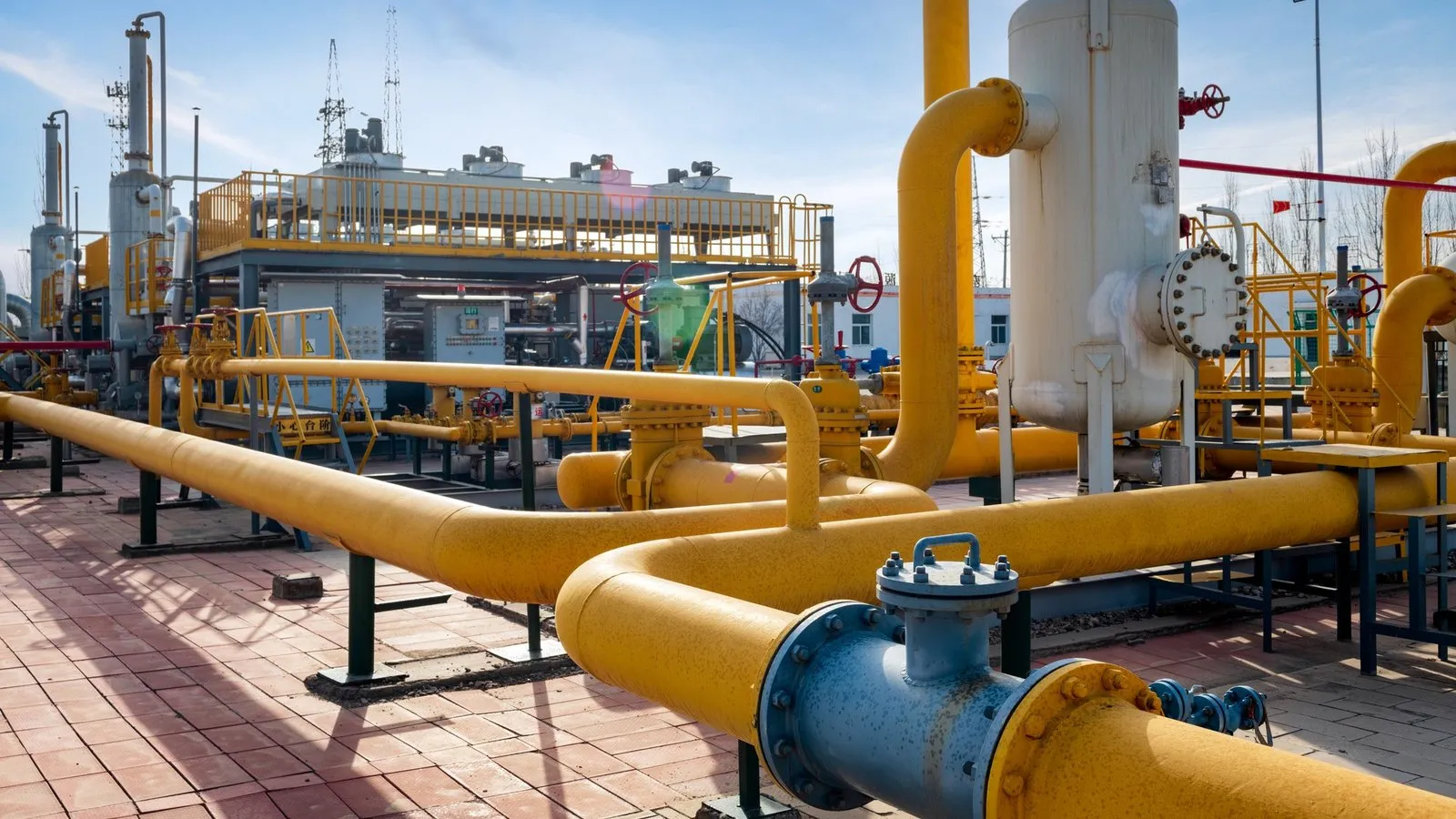
A coalescing filter separator removes from a natural gas stream the solids and liquids—water, hydrocarbon condensates, compressor oil—that travel with it as free liquid, droplets, and aerosols. It works in two stages: the first retains the solids and enlarges the fine droplets (pre-coalescence); the second separates the coalesced liquid and sends it to the drain. The goal is for compressors, burners, instruments, and meters to receive gas free of entrained liquids and solids.
This article covers the damage these contaminants cause, how each stage works, what happens inside a coalescing medium, when to change the elements, and how to replace them in a unit that is already installed.
Why liquids and solids must be removed from natural gas
Gas leaving a well, a treatment plant, or a compressor carries two types of contaminants:
- Liquids: water, hydrocarbon condensates, compressor lubricating oil, and traces of glycol or amines from the treating units.
- Solids: sand and pipe corrosion products, such as iron oxide and iron sulfide.
Liquid travels in three forms: as free liquid or slugs, as large droplets, and as aerosols, droplets so fine—many of them below one micron—that they follow the gas flow. Aerosols form, for example, when the gas cools or expands across a pressure regulator and part of the vapor condenses, or when a compressor carries over oil.
Whatever reaches downstream equipment has a cost:
- Compressors: liquid and solids in the suction wear valves, rings, and seals.
- Burners and turbines: entrained liquid disrupts combustion and leaves deposits.
- Instruments and regulators: pilots, orifices, and sensors get fouled.
- Metering and custody transfer: liquids and deposits distort meter readings.
- Glycol and amine contactors: liquid hydrocarbons and solids promote foaming and solvent losses.
How a coalescing filter separator works: the two stages
In a filter separator, the gas enters the vessel and first passes through the first-stage elements, from the outside in. The solids stay there, and the fine droplets captured by the elements merge into larger drops: this is pre-coalescence. The gas then passes through the second stage—a vane pack or coalescing elements such as the AeroSep Coalescer and AeroSep Retrofit Coalescer—which separates that liquid. Each section has its own drain: for solids in the first and for liquid in the second. The first stage does not replace the second; it complements it.
A coalescer unit reverses the order. When it has a vane pack, the pack sits upstream of the cartridges as pre-separation for free liquid and large droplets, and the coalescing cartridges handle the fine aerosols.
| Unit | First section | Second section | Catalog applications |
|---|---|---|---|
| Filter separator | First-stage elements (AeroSep First Stage): retain solids and pre-coalesce fine droplets | Vane pack or coalescing elements: separate the coalesced liquid | Compressor suction and discharge, metering and custody transfer, glycol and amine contactors |
| Coalescer unit | Vane pack (optional): the gas changes direction and large droplets impinge, drain, and collect in the drain boot; handles free liquid and liquid surges | Coalescing cartridges (AeroSep Coalescer or AeroSep Retrofit Coalescer): separate fine oil and water aerosols | Natural gas and CNG, protection of compressors, turbines, membranes, and dryers |
How droplets form and separate in the coalescing medium
Aerosol droplets are too fine to separate by gravity or by a change in gas direction: they follow the flow. A coalescing medium captures them on its fibers—by direct interception, by inertial impaction and, in the case of the finest ones, by diffusion—and gives them room to grow. The captured droplets merge with others on the fibers, move through the medium pushed by the gas and, on the outlet side, release as large drops that fall by gravity to the bottom of the housing.
In the AeroSep Coalescer and AeroSep Retrofit Coalescer, the medium is resin-bonded glass fiber with a graded, fixed pore structure, and it is also hydrophobic and oleophobic (grade H): neither water nor oil wets it. This has three effects:
- the coalesced liquid drains instead of being held in the medium;
- the pressure drop in the saturated state—when the element drains as much liquid as it captures—stays low;
- droplet re-entrainment into the outlet gas is avoided.
For the drops leaving the medium to fall rather than return to the stream, the gas velocity around the elements has to be low. That is why the number of elements is calculated from the flow rate, pressure, temperature, and composition of the gas, and why high flow rates call for horizontal multi-element vessels, which maintain the flow velocity per element.
AeroSep First Stage, AeroSep Coalescer, and AeroSep Retrofit Coalescer: what each element does
AeroSep First Stage, first stage. Dual-layer pleated glass microfiber—prefilter and final filter in the same cartridge—on polyester and mesh supports that stiffen the pleat pack and keep it from collapsing under the solids load. The gas enters through the outer face: the first layer retains the coarse contaminant and the second defines the rating. The medium can be standard, hydrophobic, or oleophobic, depending on the entrained liquid. It is offered in 3.00, 4.50, and 5.50″ diameters and in lengths from 12 to 79″, and it operates up to 120 °C (248 °F).
AeroSep Coalescer, standard coalescer. Pleated cartridge, 4″ (101.6 mm) in diameter, in 10, 20, 30, and 40″ lengths, with a 226 O-ring open end, a closed end with a removal handle, and glass-fiber-reinforced nylon end caps. The extended pleated area prolongs its service life and gives it fast recovery from liquid surges.
AeroSep Retrofit Coalescer, replacement coalescer. The same grade H medium in the dimensions of other manufacturers’ elements: 57, 70, and 152 mm in diameter, in 5, 10, 30, and 40″, with an SOE seal using a piston or internal O-ring, or a DOE seal with a flat gasket. There are versions for standard service (< 250 psig) and for high pressure (> 250 psig), with a core and cage sized for that condition.
When to change the elements: differential pressure
The condition of a filter separator is read from the differential pressure (ΔP) across each stage, measured with the unit in service. At startup, record the ΔP with the new elements: it is the baseline for everything that follows.
- AeroSep First Stage: the recommended change-out is at a ΔP of 12 to 15 psid (0.83 to 1.03 bar).
- AeroSep Coalescer and AeroSep Retrofit Coalescer: the change-out value is set for each installation, based on the startup ΔP and the operating conditions.
How to read the curve:
- A coalescer goes from dry ΔP to saturated ΔP shortly after entering service and then levels off. If it keeps rising, the increase usually comes from solids reaching the medium: check the upstream stage.
- A sudden drop in ΔP can indicate a damaged element, an O-ring that is not sealing, or gas bypassing the medium. The unit must be inspected.
- If the boot drain is not working, the liquid level rises to the elements and the liquid returns to the stream. Checking the drain is part of every startup.
At each change-out, check the condition of the gaskets and O-rings, respect the orientation of the element in the housing, and keep a record of the lot number of the installed element.
Replacing elements in installed units
Many filter separators and coalescers in service use elements from other manufacturers. Switching to AeroSep does not require changing the vessel:
- The AeroSep Retrofit Coalescer keeps the diameter, length, and sealing system of the original coalescer and fits the installed housing with no modifications or additional engineering. Compatibility is verified before delivery.
- The AeroSep First Stage reproduces the dimensions and interface of the original first-stage element with its own construction, the dual-layer pleated glass microfiber. Its code translates the code of the installed element field by field—diameter, length, rating, core, gasket, and ends—and adds the medium treatment.
Three pieces of information are needed to confirm the replacement:
- The brand and code printed on the installed element.
- The outside diameter, the length, and the type of end seal.
- The operating pressure and the elastomer compatible with the fluid.
If the reference does not appear in the cross-reference tables, the AeroSep equivalent is evaluated from the code and the operating conditions.
How we help you specify the unit
To select the model, the number of elements, and the configuration, we need the flow rate, the operating pressure and temperature, and the gas composition; if the unit is already installed, also the code of the element it uses. The complete line is on the coalescers and filtration for Oil & Gas page. For your application, send us your installation data.
Frequently asked questions
Can AeroSep elements also be used for compressed air?
Yes. The AeroSep Coalescer and AeroSep Retrofit Coalescer catalogs include compressed air and instrument air among their applications, along with biogas and process gases. The AeroSep First Stage lists service and instrument air.
What filtration ratings does the AeroSep First Stage come in?
Five: 0.3, 0.5, 1, 5, and 10 µm, with 1 µm as the standard. The rating is chosen according to the solids load in the gas and the sensitivity of the downstream equipment that needs protection.
Does the line include the vessels?
Yes. The AeroSep line is completed with carbon steel or stainless steel pressure vessels designed to ASME Sec. VIII Div. 1: vertical single-element units for low and medium flow rates, and horizontal multi-element units for high flow rates. The vane pack is sized according to the flow rate and the liquid load, and it goes in both types. See our pressure vessels.


